The Zilwaukee Bridge: From the Beginning
The following pages reproduce a 1987 report issued by the Michigan Department of Transportation in response to public concerns about the safety of the Zilwaukee Bridge, then nearing completion. The text here is reproduced word-for-word from the original report and no alterations—grammatical or otherwise—have been made. |
MAKING REPAIRS
Inspections after the accident and before repairs showed that the structure was basically stable, with no significant long-term net movement or instability. The most significant problem was the damage to the pile cap, or footing, under the damaged pier. The damaged bearings could be replaced only be raising the adjoining bridge section.
About 6,000 tons of high-strength reinforced concrete was left in sound condition in the pier columns and the affected bridge deck. Localized failures appeared to be repairable. All this could be salvaged if a way could be found to restore the support at the base of the columbs. Otherwise, MDOT faced a very expensive job of demolition, followed by an even more expensive reconstruction.
State engineers and consultants went to work to devise a workable repair plan. It was determined that a new concrete footing for the damaged pier could be cast around the base of the pier columns, tied and post-tensioned with steel cables and columns.
The new footing would be supported by reinforced concrete underground columns extending down to bedrock, about 90 feet below ground level. The main question was how to accomplish the construction repair work adjacent to the factured footing, beneath the dislocated deck section and with the launching girder standing overhead. Total weight supported by the crippled pier was approximately 6,600 tons. The deep, relatively unstable soil conditions added further complications.
Work began on the repairs in the early summer of 1983 under a contract awarded to the Toebe construction company. It required temporary freezing of the earth around and beneath the fractured footing to help stabilize the crippled pier and superstructure during the repairs.
The repair can be depicted as a six-legged table, with the legs standing on bedrock and connected to a 20-foot-thick table top above the fractured footing and the piling beneath it. The frozen soil serves in place of caissons and sheet piling that otherwise would have been required, thereby reducing the amount of potentially disruptive and vibration-causing activity beneath the bridge.
The initial step in the repair process was the installation of approximately 200 refrigeration pipes in the ground. These were constructed as a pipe within a pipe, allowing circulation of refrigerated liquid down the interior pipe and back up through the annular space between the pipes, thus cooling the surrounding earth. The pipes were inserted to bedrock, in circular patters around the intended location of each leg.
Additional pipes were inserted at angles, beneath the edges of the factured footing. Still more pipes were placed in a rectangular pattern off one end of the footing to form a frozen earth cofferdam for a pit, from which, subsequently, additional pipes could be inserted horizontally beneath the footing. The pipes were connected to manifolds and then to two high-capacity refrigeration units. Temperature sensors also were placed at various locations in the ground.
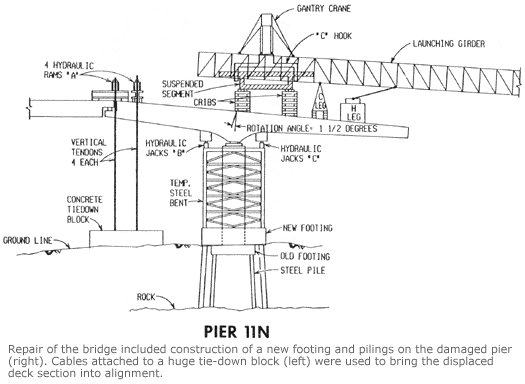
During this time period, work began on a huge tie-down block beneath the factured expansion joint. This concrete block was approximately 57 x 46 x 5-1/2 feet and weighed about 1,100 tons. Cables attached to the block from the fractured join above acted to secure the displaced superstructure from titling farther out of place. They also were used later in the construction sequence to bring the superstructure back into alignment.
The frozen earth around the base of the pier was firm enough by mid-July 1983 to allow drilling to begin for the six-foot-diameter underground columns. Six hols were drilled to and into the bedrock, and the frozen walls were used as forms for the columns, three on each side of the old broken footing. Steel reinforcement cages were positioned in the holes, and concrete was placed up to ground level.
Forms were built, and the two outside portions of the new footing were palced on top of the new underground columns. The portion above the old footing was left out at the stage, since the old footing was expected to rebound when the weight of the superstructure was removed from the columns.

A structural steel frame was fabricated and erected on top of the new footing, and fitted with 12 hydraulic jacks at the top, three at each corner, and having a lifting capacity of 600 tons each. This supplemental support system was used to support and stabilize the superstructure while additional work was completed below.
Access holes then were cut through the two-foot-thick walls of the hollow columns just above the old footing. A total of 104 holes were drilled through the column walls and the outside surfaces of the columns were roughened to increase bonding to the new footing. Forms, ducts, bar reinforcement and strand for the post tensioning were placed.
Most of the load of the superstructure was transferred to the steel frame by activating the hydraulic jacks. The central portion of the new 11-foot-thick footing was cast around the base and inside the columns. Once the new footing had gained sufficient strength and post tensioning was done, jacking was continued to lift the superstructure clear of the columns. The repaired pier, with its new footing and concrete columns to bedrock, was stronger than any of the other 51 bridge piers.
Next the damaged bearings were removed, and new bearings, weighing about four tons each, were secured and grouted in place. These new bearings had been designed to permit rotation and sliding motion to occur as the superstructure was moved back into place. After the superstructure was lowered onto the new bearings, the jacks on the side toward the expansion joint were lowered to provide clearance for rotation. Repositioning of the superstructure then began.
Hydraulic rams at the expansion joint, attached by cables to the tie-down block, were activated to draw the expansion joint downward. Each stroke of the rams dropped the expansion joint about 7-1/2 inches and raised the end of the cantilever about 10 inches. Measurements and checks wre made during and after each step. Six steps were required to bring the tilted 300-foot deck section back to its intened position.
Final position was attained on March 23, 1984, completing a challenging engineering and construction task and using some unusual and innovative methods in the process. The cost was approximately $6.8 million. Construction of the bridge would resume.
Next: Section 6: Terminating the Contract
Back to: Section 4: The Accident
Back to: Table of Contents

