The Zilwaukee Bridge: From the Beginning
The following pages reproduce a 1987 report issued by the Michigan Department of Transportation in response to public concerns about the safety of the Zilwaukee Bridge, then nearing completion. The text here is reproduced word-for-word from the original report and no alterations—grammatical or otherwise—have been made. |
TESTING AND INSPECTIONS
MDOT conducts literally thousands of tests and has devised numerous methods and devices to confirm the strength and structural integrity of the bridge, and its components, and to assure that it is being built according to design specifications. In addition to engineers and technicians at the bridge site, nearly three dozen specialists in MDOT's Materials and Technology Laboratory in Lansing have been assigned to various aspects of the project. Following are some examples.
LOAD TESTING OF SEGMENTS
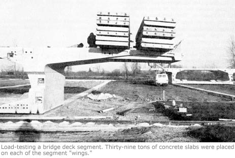
Before erection of the bridge segments began, MDOT conducted load testing in one of the first segments to be fabricated. Inspectors had observed small cracks over and above the webs, or vertical portions, of the segments at the point where they joined the outside wing, or cantilever, of the horizontal deck.
The cracks were formed during the curing cycle of the concrete when the segments were still in forms. Engineers concluded that the cause was a combination of shrinkage and thermal expansion and contraction, and were to be expected on concrete pours of that magnitude.
It was decided to test the strength of the segments. Prior to the load testing, the transverse post-tensioning of the steel cables in all segments was increased. That had the desired effect of preventing the opening and closing of the cracks under live loads.
The load test consisted of placing 39 tons of concrete slabs on the outside of each of the two wings of the segment, simulating maximum loads that can be expected when the bridge is opened. Of the 52 locations where crack widths were monitored, seven showed a very small crack opening of .002 (two one-thousandths) inches or less when the maximum load was placed. The other 45 locations showed no crack width increase, even at maximum load. Added protection will be provided by the application of a layer of high-density latex-modified concrete to the bridge deck.
OTHER TESTS
- The steel cable used to hold concrete segments together is regularly tested in the laboratory to confirm that it meets strength requirements before it is placed and post-tensioned. The same is done when the reinforcing bars in the segments, piers and footings and with the rods connecting the segments.
- The aggregate materials in the high-strength concrete are checked to confirm that they meet specifications.
- A testing program has started to check out the stresses, strains and deflections in the bridge.
- Concrete quality of each segment was thoroughly tested for strength adn for air and water content.
- When the launching girder is being advanced, close monitoring is done with instruments at selected piers to detect any movement on the piers.
- Cores were cut at verious locations to check on concrete quality.
- Soils and bedrock tests were made at the bridge site before construction began to check their strength.
- Load testing was done on steel pilings for the piers.
- Temperature measuring devices were installed inside some of the deck segments as they were being fabricated to determine that they were curing properly.
- The huge bearings between decks and piers and at the expansion joints are inspected.
- The materials in the expansion joints of the decks undergo inspection, including seals, steel plating and rubber units used to seal the joints.
- Reinforcing bars were attached to some of the bridge footings to add strength using procedures developed by MDOT.
- The launching girder used to erect the segments, and each of its members, were measured to confirm its actual weight.

Next: Section 10: Conclusion & Appendix
Back to: Section 8: Bridge Safety
Back to: Table of Contents

