
The Zilwaukee Bridge: From the Beginning
The following pages reproduce a 1987 report issued by the Michigan Department of Transportation in response to public concerns about the safety of the Zilwaukee Bridge, then nearing completion. The text here is reproduced word-for-word from the original report and no alterations—grammatical or otherwise—have been made. |
CONCLUSION
Completion of the new high level bridge at Zilwaukee will bring to a conclusion some 20 years of planning, designing and construction of one of the biggest and most complex projects ever undertaken by MDOT. It represents a significant engineering accomplishment.
The project has encountered problems, some of them serious and most of them related to the 1982 accident. There have been no serious injuries and no lives lost, however, and the project, including the knowledge gained from the repair process, has provided much engineering experience of value to the entire highways industry.
The bridge, when completed, will be safe, durable and efficient, ready to serve the motoring public for many years to come. It will replace an obsolete, inadequate drawbridge that has caused numerous accidents and endless traffic delays over the years. And it will easily accommodate the more than 31,000 vehicles that travel along that section of I-75 freeway every day.
APPENDIX
ZILWAUKEE BRIDGE CONSTRUCTION INVOLVES:
Michigan Department of Transportation (MDOT)
Has responsibility for the design, construction and maintenance of the 9,500-mile
state highway system--all the Interstate and US- and M-numbered highways.
U.S. Department of Transportation and the Federal Highway
Administration (FHWA)
FHWA, a part of U.S. DOT, administers the U.S. Highway Trust Fund, which provides
90 percent of the money for Interstate System projects.
S. J. Groves & Sons, Minneapolis, Minn.
Prime contractor for the final construction of the Zilwaukee Bridge.
Howard Needles, Tammen and Bergendoff, Kansas City,
Mo.
A private consulting engineering company retained by MDOT to provide expertise
in construction of the bridge.
T. Y. Lin International, San Francisco
A private consulting engineering company retained by S. J. Groves & Sons as
its consultant at the bridge.
ZILWAUKEE BRIDGE FACTS AND FIGURES
Owner: Michigan Department of Transportation (MDOT).
Designer: Bouvy, van der Vlugt & van der Niet/Segmental Technology & Services (BVN/STS), Indianapolis, Ind.
Length: 8,066 feet northbound, 8.090 feet southbound.
Width: Two roadways, northbound and southbound, each 70 feet, 10 inches wide, allowing for four traffic lanes and an 11-foot, 5-inch shoulder in each direction. There is a 5-foot, 3-inch separation between the two roadways (superstructure decks).
Underclearance: 125 feet above the Saginaw River (slightly higher at mid-point).
Design: Segmental concrete using 1,592 pre-cast concrete segments fabricated in a plant built on the bridge site. Each segment averages 10 feet in length, is 73.5 feet wide and weighs up to 160 tons. They are erected using a post-tensioned system of steel cables, supplemented by epoxy for joint sealing. There are 25 spans on the northbound bridge and 26 on the southbound bridge, varying in length from 155 to 392 feet. In addition, the bridge will have a 405-foot long, three-span ramp bridge to carry traffic onto the southbound roadway.
Substructure: Two-column vertical concrete piers supported by 200-ton capacity pilings. There are 52 such piers supporting two roadways.
Materials Quantities: Approximately 150,000 cubic yards of concrete, 22 million pounds of reinforcement steel, 4,000 miles of half-inch steel cables.
Scheduled Completion: 1988.
Traffic: Existing four-lane drawbridge carrying I-75 over the Saginaw River was designed for 20,000 vehicles daily. Current traffic is approximately 31,000 daily.
Current Contractor on the Bridge: S. J. goves & Sons of Minneapolis, Minn.
Status of Construction of May 1, 1987: The bridge is about 80 percent completed. A total of 1,233 of the 1,592 concrete segments have been erected. The northbound bridge is completed except for the outside railings and special concrete covering to be placed on the bridge deck.
Consultants: The contract requires both MDOT and the contractor to have consultants on the bridge site during the construction. The department's consultant is Howard Needles, Tammen & Bergendoff of Kansas City, Mo. Contractor's consultant is T. Y. Lin International of San Francisco.
Bridge Cost: $117.5 million, less the amount to be realized from the sale of the department-owned fabrication plant and equipment. This is estimated to be worth at least $3 million. Another $9.8 million will be spent on approaches and ramps.
| COST BREAKDOWN: | |
| Paid on the original contract with Stevin Construction of The Netherlands and Walter Toebe Construction Co. of Wixom | $74.8 million |
| Cost of repairs following the 1982 construction accident | $6.8 million |
| Bid price on current contract | $35.9 million |
| Federal funds are paying 90 percent of the cost. | |
Safety Measures:
— The bridge is built to carry more than double the heaviest traffic load
expected during the worst traffic jams.
— In addition to the traffic load, the bridge is built to carry its own weight plus an additional one-third of its weight.
— During construction, the bridge gets its most severe safety test almost every day. Structurally, the bridge is weakest during construction, yet it is now carrying loads far greater than it will ever carry when opened to traffic. The equipment used to attach new segments to the bridge, plus the truck loaded with a segment, weighs about 1,962 tons--nearly 4 million points. To create the same weight in the same space on the bridge would require lining up 49 fully loaded 18-wheel trucks and trailers bumper-to-bumper across four lanes.
— Specifications for the bridge deck segments require concrete strength of 6,000 pounds per square inch (psi), compared to 4,500 psi for other bridges on the state highway system. The actual strength of the concrete is 10 percent higher than 6,000 psi and runs as high as 7,700 psi.
— To protect them from corrosion, all the high-strength, post-tensioned steel tendons inside the bridge are completely encased in concrete.
— A special covering of latex-modified concrete will be placed on the bridge deck, providing further protection against corrosion.
— A non-corrosive salt substitute--calcium magnesium acetate--will be used for snow and ice control after the bridge is opened to traffic.
— The epoxy used as joint sealant is fire-proof and, when it hardens, is stronger than concrete.
Maintenance and Inspections: MDOT is developing
an intensive maintenance plan for the bridge for use once it is opened
to traffic. It will be based on a detailed maintenance manual of the type
that has been developed for other major bridges, including the Mackinac
Bridge, International Bridge and the Blue Water Bridge. MDOT will hire
an expert consultant to do a maintenance inspection on the bridge at least
every other year. In addition, a special MDOT design and engineering team
will make inspections throughout the year.
PRE-CAST CONCRETE SEGMENTAL BRIDGES:
Bridges under design, under construction or open to traffic as of December 1981
| State/Province | Bridge | Location |
| Alabama | Dauphin Island | Mobile County |
| Alaska | Gastineau Channel | Juneau |
| Arkansas | Onachita River | |
| British Columbia | Knight Street, North Channel | Vancouver |
| British Columbia | Knight Street, South Channel | Vancouver |
| California | Pine Valley Creek | |
| California | Parrotts Ferry Stanislaus River | |
| Colorado | Vail Pass Black Gore Creek | |
| Colorado | Vail Pass, Miller Creek | |
| Colorado | Vail Pass, I-70 | Side Hill |
| Colorado | Vail Pass, I-70 | Gore Creek |
| Florida Keys | Seven Mile | |
| Florida Keys | Long Key Channel | |
| Florida Keys | Channel No. 5 | |
| Florida Keys | Niles Channel | |
| Georgia | NW Ramp, I-285 & I-85 Bridge No. 4 | Atlanta |
| Georgia | W Ramp, I-285 & I-85 Bridge No. 2 | Atlanta |
| Georgia | I-85 Viaduct, Nos. 28 and 29 | Atlanta |
| Hawaii | Kipapa Stream, H2 | |
| Idaho | Lewiston Clarkston | Washington |
| Idaho | North Fork Payetter River | |
| Illinois | Kishwaukee River | Rockford |
| Indiana | Cline Avenue | Indana Harbor |
| Indiana | Turkey Run Creek | Parke County |
| Indiana | Muscataturk River | Jennings County |
| Indiana | Sugar Creek | Parke County |
| Indiana | Wabash River | Covington |
| Kentucky | Kentucky River | Franklin County |
| Louisiana | Red River | Boyce |
| Maine | Sheepscot River | |
| Michigan | Muskegon River | US-131 |
| Michigan | Zilwaukee High Level | Saginaw County |
| Minnesota | Plymouth Avenue | Minneapolis |
| Minnesota | Minnesota River | Bloomington |
| New York | Genesee River | Rochester |
| New York | Main Line Viaduct and Ramp | Syracuse |
| North Carolina | Linn Cove Viaduct | Avery County |
| North Dakota | Bismarck Avenue, Missouri River | Bismarck |
| Nova Scotia | Dr. C. L. Goose, Shubenacadic River | |
| Nova Scotia | Bear River | Annapolis Cty. |
| Ohio | North Main St. Viaduct | Akron |
| Ontario | Mullet Creek | Mississauga |
| Ontario | Twelve Mile Creek, Southbound | St. Catharines |
| Ontario | Twelve Mile Creek, Northbound | St. Catharines |
| Ontario | Islington Avenue, Overpass | Toronto |
| Ontario | Credit River | Mississauga |
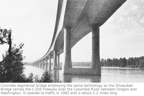
| Oregon | I-205 Columbia River | Portland |
| Pacific | Koror-Babelthaup | US Trust Territory |
| Puerto Rico | Caguana River | Utaudo |
| Quebec | Aux Mulets River | St-Adele |
| Quebec | Du Kievre River | Notre-Dame du Laus |
| Quebec | Kinojevis River | Joannes |
| Quebec | Matapedia River | Milnikek |
| Quebec | Rimouski River | Rimouski |
| Quebec | St. Maurice River | Grand-Mere |
| Tennessee | South Knoxville Blvd., Alternate A | Knoxville |
| Tennessee | South Knoxville Blvd., Alternate B | Knoxville |
| Tennessee | South Knoxville Blvd., Alternate C | Knoxville |
| Texas | Houston Ship Cannel | Houston |
| Texas | JFK Memorial Causeway | Corpus Christi |
| Washington | Denny Creek | |
| Washington | Duwamish River, West Seattle Freeway | |
| Washington | Columbia River, SR-182, Pasco | Richland |
| Source: Federal Highway Administration, Washington D.C. |
||
Back to: Section 9: Testing and Inspections
Back to: Table of Contents